Transient Response of Series Rlc Circuit
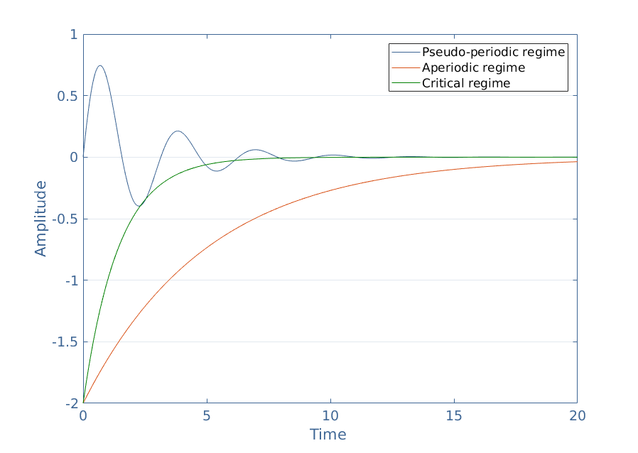
R L C Vt scope V R V L V C According the Kirchhoffs law V R V L V C Vt-10 -0. These drawings are unified when L 1 C 1 and ω 0 1.

Capacitor Simulating All Transient Solutions For Rlc Series Circuits Electrical Engineering Stack Exchange
The figure shows the underdamped and overdamped responses of the series RLC circuit.
. V0 is the voltage just after time t 0. Diode 23 Design and Analysis of Diode Circuits 24 BJT 25 BJT cont 26 BJT cont 27 Quiz 3 28 Op Amp 29 Op Amp cont. The transient response curve of RC circuit increases and is shown in Figure 3.
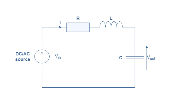
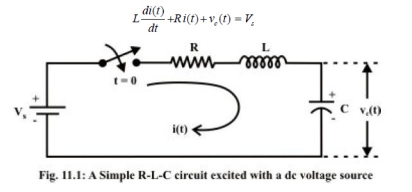
Since the R L and C are connected in series thus current is same through all the three elements. R L C V scope Resistance R Ohm Capacitance C uF 10-6F Inductance L mH 10-3H Transients in RLC circuit. Lab 12 Transient Response of Series RLC Circuits using Multisim RLC circuits have transient responses to changes in applied voltage or current.
The resulting current I RMS is flowing in the circuit. Second-order differential equation of the series RLC circuit. Where v1 is the new steady-state voltage.
The solution to such an equation is the sum of a permanent response constant in time and a transient response V outtr variable in time. Series RC circuit. The results show what would happen if the load was attached while the supply was still powering up.
Transient Response of RLC Circuit. This lab is similar to the RC Circuit Lab except that the Capacitor is replaced by an Inductor. Study the transience due to inductors using a series RL circuit and understand the time constant concept.
1 Equation 1 is a second order linear homogenous differential equation. Is the time. V c t V 1 e t R C t 0.
Transient response for a voltage is given by vt v1 v0 v1e t. In the preceding lesson our discussion focused extensively on dc circuits having resistances with either inductor or capacitor ie single storage element but not both. Where V is the applied source voltage to the circuit for t 0 and R C τ is the time constant.
Consider the circuit consisting of R L and C connected in series across a supply voltage of V RMS volts. So in this video the transient response for the series and parallel RLC Circ. Transient responses of RLC circuits are examined when subjected to both long time scale relative to the decay time square wave voltages and sinusoidally vary- ing voltages over a range of frequencies about the resonant frequency.
Transient Response of First Order Circuits 21 Transient Response of Second Order Circuits 22 Circuits with Non-linear Elements. The characteristic equation then becomes. Transient RLC Response Without Operating Point.
TRANSIENT RESPONSE OF RLC CIRCUITS. April 21st 2019 - A RC RL RLC circuit can be used as a filter oscillator and much more it is not possible to cover every aspect in this tutorial so we will learn the basic behaviour of them in this tutorial Basic Principle of RC RL and RLC circuits Natural and Step Response of Series amp Parallel RLC April 7th 2019 - Natural and Step Response. We will analyze this circuit in order to determine its transient characteristics once the switch S is closed.
The type of response is determined by the components in the circuit. First simulate without the operating point to show the combined response of the supply powering up and the load attached after 1 second. EE 201 RLC transient 10 Overdamped response The transient will consist of two decaying exponentials.
The permanent response is easy and obvious to find the solution V out V in is indeed a permanent solution of Equation 1. Change the load to the RLC series circuit and analyze the results. Transient Response of RL Circuit Objective.
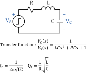
When s 1 and s 2 will be both be real and negative. The time constant in an RLC circuit is basically equal to 𝛽 but the real transient response in these systems depends on the relationship between 𝛽 and 𝜔0. CIRCUITS LABORATORY EXPERIMENT 6.
Dynamic response of such first order system has been studied and discussed in detail. The responses can be Critically Damped Overdamped or. The critical damping is drawn with a thick red curve.
Series RLC Circuit. The presence of resistance inductance and capacitance in the dc circuit. Second-order systems like RLC circuits are damped oscillators with well-defined limit cycles so they exhibit damped oscillations in their transient response.
12 What is Transient Response of RLC Circuit. Derivation of Transient Response in RLC Circuit with DC. From Kirchhoffs laws it can be shown that the charging voltage V c t across the capacitor is given by.
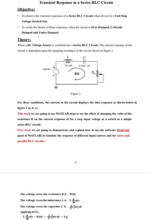
When switch S is closed at t 0 we can determine the complete solution for the current. Application of KVL at t 0 in figure 1 after switch is closed gives. In this video you will learn about the transient analysis of the RLC circuit.
Analysis and Example Problems. A one-way trip from V i to V f. According to the value of different damping coefficient ζ the solution of the differential.
Transients in RLC circuit. WikiZero Özgür Ansiklopedi - Wikipedia Okumanın En Kolay Yolu. Derivation of Transient Response in Series R-L Circuit with Sinusoidal Excitation Let v V m sin ɷt ϕ where ϕ varies from 0-2p depending on the switching instant.
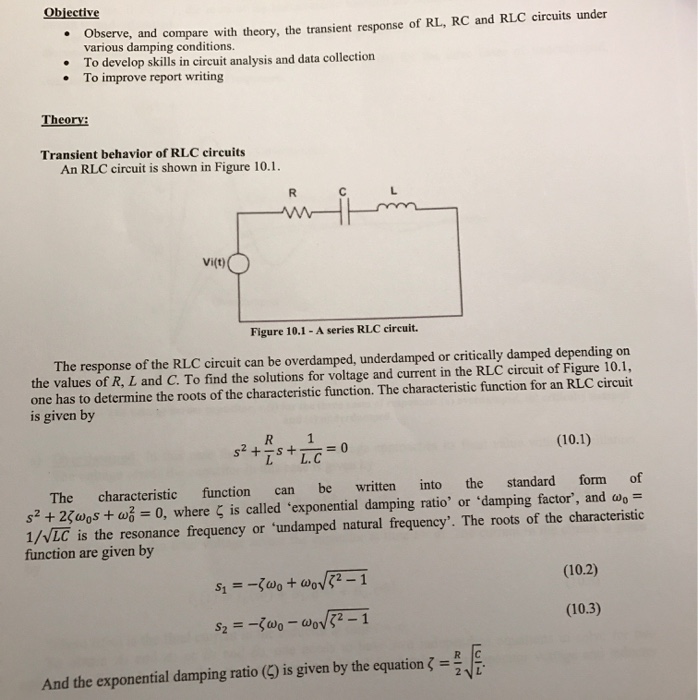
The capacitor and inductor are initially uncharged and are in series with a resistor. NI ELVIS Resistor 1 KW Inductor 33mH Theory. Transient Response Series RLC circuit The circuit shown on Figure 1 is called the series RLC circuit.
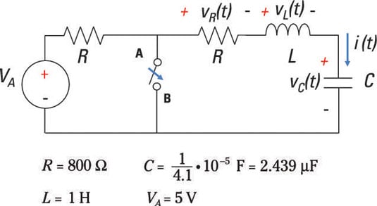
S 1 5000 s1 τ 1 02 ms and s. Consider a Transient Response of RLC Circuit consisting of resistance inductance and capacitance as shown in Fig. Application of KVL in the series RLC circuit figure 1 t 0 after the switch is closed leads to the following differential equation.
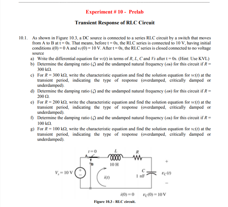
R 2L 1 LC v C t Aes 1 t Bes 2 t V f V f V i es 1 t s 1 s 2 1 es 2 t s 2 s 1 1 V f For V i 0 V V f 10 V R 250 Ω L 10 mH and C 1 µF. A transient response or natural response is the response of a system to a change from equilibrium.
![]()
Transient Response Of Rlc Circuit
Analyze An Rlc Circuit Using Laplace Methods Dummies
Series Rlc Circuit Analysis Electronics Lab Com
![]()
Transient Response Of The Capacitor Voltage When The Square Wave Source Download Scientific Diagram
Step Response Of An Rlc Circuit
Series Rlc Circuit Analysis Electronics Lab Com
Transient Response Of Rlc Circuits
![]()
File Rlc Transient Plot Svg Wikipedia

2nd Order Transient Analysis Series Rlc Circuit Youtube
Transient Analysis Of The Rlc Circuit With Examples Youtube
![]()
Transient Response In Rlc Circuit With D C Excitation

2nd Order Transient Analysis Series Rlc Circuit Circuit Analysis Youtube

Ee 2715 Second Order Circuits Step Response Of Series Rlc Circuits Youtube

Step Response Of A Series Rlc Circuit Calculator

Series Rlc Circuit And Rlc Series Circuit Analysis
Solved Transient Response In A Series Rlc Circuit Objective Chegg Com
Solved Experiment 10 Prelab Transient Response Of Rlc Chegg Com
Solved And Compare With Theory The Transient Response Of Chegg Com
Rlc Circuit Learn Ltspice


Comments
Post a Comment